






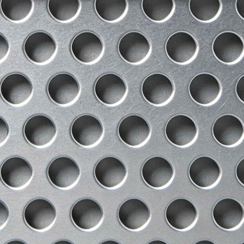
Perforated Metal Panel Installation Standards, Construction Guidelines & Engineering Acceptance Criteria
🧠 Perforated Metal Panel Construction Standards
Installation Guidelines, Engineering Procedures & Quality Acceptance Criteria (Full Technical Guide)
Perforated metal panels are widely used in industrial ventilation systems, architectural façades, acoustic engineering, equipment protection, and building envelope systems due to their:
- high structural integrity
- controllable open area ratio
- excellent corrosion resistance
- stable mechanical performance
- strong architectural adaptability
According to GB/T 10612-2003 (Metal Perforated Sheet Standard), the final engineering quality of perforated metal systems is determined not only by material manufacturing accuracy but also by installation process control and acceptance standards.
📌 Reference standard:
https://www.iso.org/standard/63587.html (ISO perforated metal related structural standards overview)
1. ENGINEERING IMPORTANCE OF INSTALLATION QUALITY
In real engineering applications, most defects such as:
- panel deformation
- air leakage
- water seepage
- corrosion acceleration
- façade unevenness
are not caused by material defects, but by non-standard installation practices and improper system design execution.
📌 Engineering principle:
Installation quality is the final determinant of system performance stability.
2. PRE-CONSTRUCTION ENGINEERING PREPARATION SYSTEM
Proper preparation ensures structural accuracy and eliminates hidden installation risks.
2.1 Site Measurement and Structural Evaluation
Before installation, engineers must verify:
- structural dimensions
- vertical and horizontal alignment
- load-bearing capacity of substrate
- steel frame or wall support strength
- installation clearance and tolerances
For façade systems and high-rise applications, wind load resistance is critical.
📌 Wind load engineering reference:
https://www.engineeringtoolbox.com/wind-load-d_1974.html
📌 Key insight:
Dimensional deviation at the base level propagates into full structural misalignment after installation.
2.2 Incoming Material Inspection System
All perforated panels must be checked for:
- thickness tolerance compliance
- hole diameter accuracy
- pitch consistency
- open area ratio stability
- surface coating quality
- flatness and deformation
Surface defects such as scratches, oxidation, or coating failure must be rejected.
📌 Metal coating durability reference:
https://www.astm.org/standards/a123.htm (Hot-dip galvanizing standards)
2.3 Fastener & Accessory Compatibility System
Fastener selection must follow material compatibility engineering rules:
- galvanized panels → galvanized fasteners
- stainless steel panels → stainless steel fasteners
- aluminum panels → anti-corrosion isolated fasteners
This prevents galvanic corrosion, which occurs when dissimilar metals are in contact.
📌 Corrosion engineering reference:
https://nickelinstitute.org/about-nickel/corrosion/
2.4 Tools & Site Preparation System
Required tools:
- laser level systems
- precision measuring tools
- cutting & grinding equipment
- drilling tools
- scaffolding systems
- sealing equipment
Site preparation includes:
- removal of dust, oil, and debris
- leveling uneven surfaces
- safety zoning for high-altitude work
3. STANDARD INSTALLATION PROCESS FLOW
Installation must follow a strict engineering workflow:
3.1 Layout Positioning System
Using laser alignment:
- structural grid lines
- fastening reference points
- frame installation boundaries
📌 Engineering rule:
All installation lines must be geometrically consistent to avoid cumulative deviation.
3.2 Structural Frame Installation System
Frame systems include:
- steel frame
- aluminum alloy frame
- light steel keel systems
Key parameters:
- spacing: 300–500 mm
- anchoring: expansion bolts or welded joints
- leveling tolerance: controlled within engineering standards
📌 Structural engineering reference:
https://www.sciencedirect.com/topics/engineering/steel-frame-structure
3.3 Panel Cutting & Edge Processing System
On-site cutting is required for:
- edges
- corners
- irregular geometry areas
After cutting:
- burr removal
- edge polishing
- deformation correction
📌 Engineering insight:
Edge defects are the primary source of stress concentration failure.
3.4 Panel Fixing System
Installation principle:
- center-first fastening
- symmetrical load distribution
- uniform fastener spacing (≤200mm)
Expansion gaps:
- indoor: 1–2 mm
- outdoor: 3–5 mm
📌 Thermal expansion reference:
https://www.azom.com/article.aspx?ArticleID=3082
3.5 Sealing & Waterproofing System
Outdoor applications require:
- silicone weather sealing
- joint waterproofing
- interface sealing
- frame-edge protection
📌 Sealant engineering reference:
https://www.sika.com/en/solutions_products/industry/building-sealing.html
3.6 Final Cleaning & Inspection System
Includes:
- surface cleaning
- alignment verification
- fastening inspection
- vibration check
- visual uniformity evaluation
4. APPLICATION-SPECIFIC INSTALLATION REQUIREMENTS
4.1 Building Façade Systems
Focus:
- wind resistance
- waterproof integrity
- architectural uniformity
📌 Reference (façade engineering systems):
https://www.designingbuildings.co.uk/wiki/Facade_systems
4.2 Industrial Ventilation Systems
Focus:
- airflow efficiency
- vibration resistance
- equipment compatibility
📌 HVAC ventilation reference:
https://www.engineeringtoolbox.com/air-conditioning-ventilation-systems-d_202.html
4.3 Grain Storage Ventilation Systems
Focus:
- airtight sealing
- load-bearing flatness
- corrosion protection
4.4 Ceiling Installation Systems
Focus:
- lightweight structure
- alignment accuracy
- aesthetic continuity
5. COMMON INSTALLATION PROBLEMS & ENGINEERING SOLUTIONS
Typical issues:
- panel deformation → structural reinforcement or replacement
- uneven gaps → repositioning or recalibration
- loose fasteners → re-locking and reinforcement
- sealing failure → resealing system
- surface damage → repair coating or panel replacement
📌 Engineering principle:
Failure correction must be system-based, not point-based.
6. ENGINEERING ACCEPTANCE STANDARDS
Final acceptance includes:
6.1 Appearance Inspection
- no scratches or defects
- uniform perforation alignment
- clean sealing lines
- consistent surface finish
6.2 Structural Inspection
- no deformation
- no looseness
- stable frame system
- correct alignment
6.3 Functional Inspection
- airflow meets design parameters
- no blockage or turbulence anomalies
- stable acoustic performance
6.4 Safety Inspection
- secure fastening system
- corrosion protection intact
- structural load compliance
FINAL ENGINEERING CONCLUSION
Perforated metal panel installation is a system-level engineering process integrating structural mechanics, airflow control, corrosion engineering, and architectural alignment principles.
Ultimate Engineering Principle:
The performance of a perforated metal system is not finalized at manufacturing—it is determined during installation and system integration.